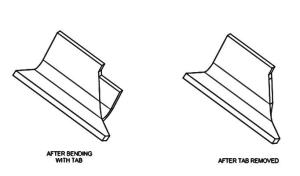
Improved design of sheet metal bend and edges
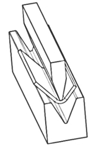
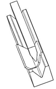
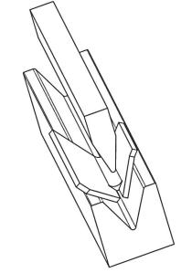
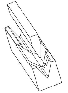
Sheet metal is bent in a press brake by a top ram pushing the middle of the work piece down into the valley in a lower die. This works best when the edges of the metal are perpendicular to the bends. There must be enough material on each side of the bend to bridge the gap in the lower die.
The sheet metal is not equally supported on both sides if the edge crosses the bend line on an angle. The bend near the end will be irregular and deformed.
One method to accommodate an angled edge is to split the sheet metal on the bend centerline. The split should extend far enough so that the bend area is full supported on both sides of the die. The portion along the split remains straight and is outside of the bend curve. This is more pronounced when bending past 90 degrees. After bending it is often necessary to weld the split closed and to grind the area to a matching contour.
A method I developed is to cut the flat piece with extra material in the bend area. This material assures that the whole bend length is fully supported resulting in a consistent bend. After bending, the extra tab is cut off giving the desired edge. The desired edge can be scribed or inked in the flat. The desired edge could also be marked by a series of perforations to aid in the cutting.
The resulting geometry with the extra tab is better than with the split method. Less labor is required. Although the cutting is hand work, there is not as much hand work as in finishing the bend with a split. Grinding the tab does not require as much skill as welding the gap and then grinding the weld. Better results, lower costs.
Knowledge of the process steps used in the common designing enabled me to see how things could be better. Like many improvements, it seems obvious once it is tried. It was a novel approach to leave material in place to be removed later after it helped the forming process. This approach is gaining acceptance.
